Recently, we received multiple email contacts from people in Brazil who had viewed a YouTube video that appears to offer some critical analysis of our Genesis YPbPr cable. Unfortunately, this person did not reach out to us first, so we had no chance to have a back and forth about its content before it was published. The video is in Portuguese, so we don't know exactly what is being said, but one of the emails we received appears to do a decent job of breaking down the important points. While we have some reservations about even posting a response (do we have to do this every time someone creates a video like this?), since much time was spent analyzing the claims within the video to respond in detail to the emails we received, we figured it could be enlightening for others to read. Here's an edited-for-blog version of our email response to the person who gave us the breakdown. For full disclosure, we made some minor edits, changed some of the photos, and rephrased some of the explanations for a more generic audience. For those of you like us who are deficient in Portuguese language comprehension, the main claim in the video is that the video outputs are out of spec:
The email we received states: He first measures each signal with the contrast switch turned off and gets the following measurements: Y = ~1.06V, Pb = ~640mV, Pr = ~620mV. He tells that the Y signal is within recommended level because it's delivering 700mV of video signal plus 300mV of sync signal on this line. But he says Pb and Pr are below the recommended level of 700 mV.
Thank you for giving us the breakdown and taking the time to do so. Now I can actually understand the content of the video. I did watch the video in its entirety after I read your summary, just to make sure I wasn't missing any context in the test setup. As you would expect, I have many problems with the way the testing was done, but I think my objections are justified (you can decide yourself). Some are major points, and some are minor, but I won't go into detail categorizing them as such below.
1.) When doing a video like this showing measurements down to millivolts, I personally would start by showing a rough DC validation to instill confidence in the viewer. Many oscilloscopes drift in DC accuracy (offset and gain) over time, which is why there's a whole equipment calibration business out there with equipment calibrated annually. Anyway, I typically set a DC power supply to 1 volt or less, measure it with a known accurate DC multimeter, and then see how close the oscilloscope measurement is to the meter measurement. It doesn't have to be exact, but it's nice to have it within ±30mV. Offset error (more common) is likely to be constant, so you can add/subtract it in your subsequent measurements.
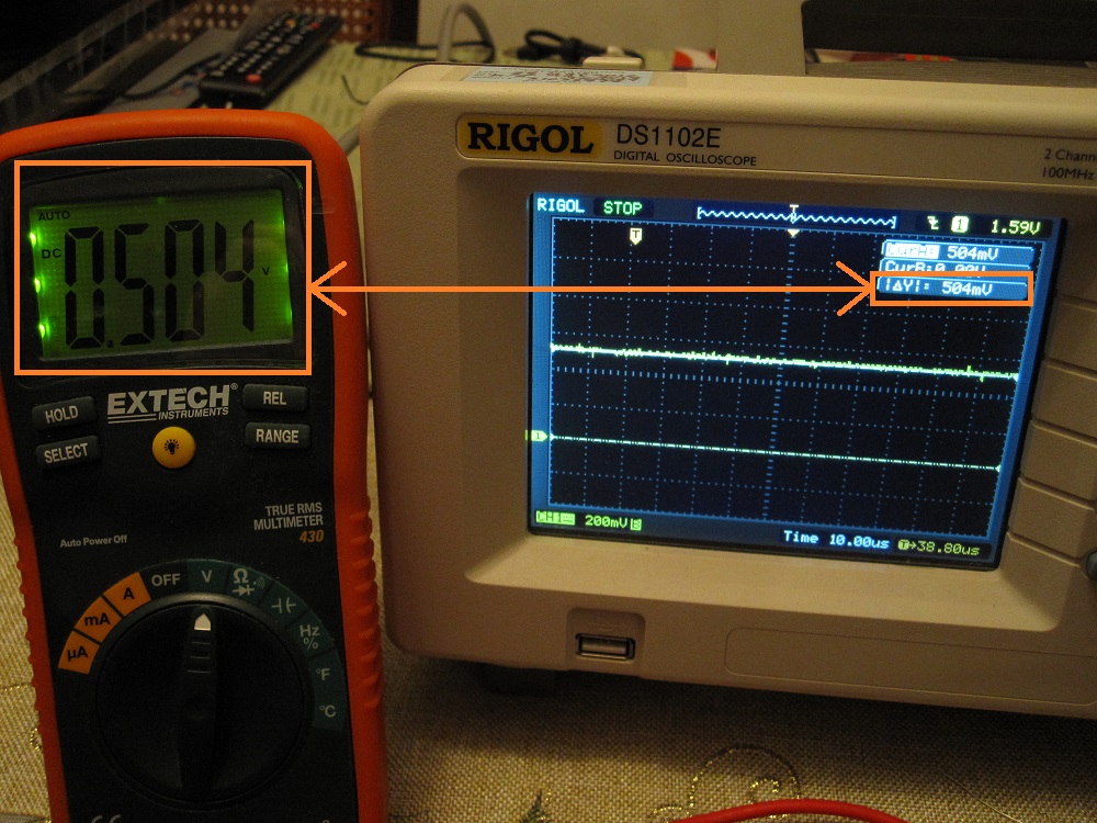
Basic oscilloscope verification
2.) The way the measurement is being done on the scope is prone to much error. He's using the auto-measurement tool to measure peak-to-peak voltage. A few problems here. First, the timescale is set way too wide, showing several frames of video within the small measurement window of the scope when we only need to measure a single line. The auto-measurement tool has a finite time-precision so on a signal that's changing a lot within the capture window, it's not always going to be landing its time-samples where you need them to. Plus, any random noise spikes or ringing on video edges can be reported if a sample happens to land on such an area. You can see evidence of how poor this method is by how much the measurement on screen keeps changing, up to around 40mV (that's around 15 RGB values in an RGB 0-255 system). The proper way to do this is to zoom into a couple lines of video, and use the manual cursors at the top and bottom of the video waveform to get the delta, since you should know where these are and what you're looking at. I attached an example for you:

Plot from oscilloscope (same as verified above) of Sega Nomad using Genesis YPbPr cables. This is the Pr signal during a proper 100% colorbar pattern. Notice how the auto-measurement (red - incorrect) is higher than the cursor measurement (green - correct).
3.) The colorbar test pattern being used is suspicious. First, it's being described as a SMPTE colorbar pattern which implies that all the vertical bars are 75% of the maximum levels. However, the Genesis is incapable of generating something at exactly 75%, due to its low color bit-depth (3-bits per color channel). The closest you can get is 5/7 = 71.43%. This is what our own test software uses to approximate 75% bars. However, let me make the assumption that this "hacked Sonic ROM" that is being used might actually be generating 6/7 = 85.71% bars. If we take the value of Pr he measures and apply the inverse of 0.8571 to correct it, let's see what we get: 620mV / 0.8571 = 723mV. This is much closer to ideal, but it doesn't account for all the other caveats I'm outlining in my other numbered points.
The justification for why I think this is the case can be seen in the video itself. Notice how the white bar is darker than the white square at the bottom of the screen. That square is true-white while the bar is not. It also can be seen on the oscilloscope, and the square is the reason why the luma measurement on the scope is close to ideal while the Pb/Pr ones are much lower. The method of of auto-measuring (outlined above) captures the white square and ignores the white bar since it's shorter in height. I attached some snips for you to show you what I'm talking about:

Snips explaining which parts of the video signal correspond to what is actually shown on the screen.
When measuring YPbPr video levels, it's proper practice to use a non-SMPTE pattern which is 100% saturation on all the vertical bars, adds a black vertical bar at the end, and also removes the junk on the bottom which is meant for CVBS and S-Video systems. This is stated clearly in the CEA-770.2-D specification. We actually got permission from CEA to post the relevant figure from their controlled document, and it's shown on our FAQ page: http://www.hdretrovision.com/faq#standards
I don't know why this hacked Sonic ROM was chosen in the first place. Our own test software is clearly the correct choice for this type of test, since all the source code is available in case someone questions the validity of the pattern generation. This ambiguity is the reason why we write our own software. We only trust things to be done correctly if the underlying fundamentals are understood, and therefore important caveats like the inability for the Genesis to generate exactly 75% are known to us.
4.) Various consoles have minor variation in their RGB signal output. For the darker switch setting, we based our gain adjustment across measurements from 18 different Genesis console revisions/variants and 6 Sega Master System revisions/variants. Generated RGB signals seem to vary between 635mV and 715mV, including a slight variation of a few ohms of source impedance. We used weighted averaging to try to make every console as close to 700mV as possible on the resultant Y, Pb, and Pr outputs after gain & offset correction. Although I'd like it to be true, there's no way to be 100% perfect in every case. I should also mention we have never explicitly tested and/or measured a Mega Drive from Brazil, as is reflected in our verified console compatibility list. My gut tells me it's not going to be much different than anything else, but I think it's worth pointing out.
5.) (The email we received states: "He then mentions the contrast switch is a good feature of the cable because CRT works better with 1V on the Y line while LCD screens work better with 1.3~1.4V on the Y line, so it's good to have that option.") I don't agree with the "better for LCDs" statement. There are objective video levels set forth in CEA-770.2-D (similar to EBU-N10-1998 which is free to view) for YPbPr video which all consumer electronics products are supposed to adhere to. I suspect much of the confusion here is related to the 75% colorbar problem described earlier. I think he's incorrectly assuming the white bar is supposed to be white, when in reality it's some fraction of white. Flipping the contrast switch to the brighter setting will incorrectly boost this bar back towards 100% white. In fact, that particular switch setting on our cable is only meant to be used with older revision Sega Master System consoles, which have very weak video output. We measured the weak Sega Master System consoles to have an RGB output around 475mV. This SMS correction is the true purpose of the switch feature on the Genesis cable, and should only be used with these consoles. I had another email asking if the higher output levels when using the wrong console will damage anything, which is a valid question. The extra voltage won't damage the circuit in the cable, since it can handle much more than we're using it for. On the TV/display input side, the extra RMS power dissipated in the 75Ω termination resistor is negligible (few milliwatts). Also, video input stages these days typically run off 3.3V or higher supplies, and have clamping protection if anything is beyond those rails. Therefore, the only thing you would experience is clipping/saturation of the video signal (i.e. it will look bad and washed out).
6.) (The email we received states: "He says that, ideally, the contrast switch should affect only Luma signal, not color, and that color levels get above the recommended level anyway. He then speculates that the circuit used on the HD Retrovision cable is regulating the RGB signal levels on the input side to save costs with buffering (?), because it should have a buffer for each channel and the buffer should amplify the [output] signal instead of amplifying it on the input.") The statement about how contrast (gain adjustment) is applied only to the luma channel demonstrates a fundamental misunderstanding of video systems. Historically, these have always been applied in the RGB colorspace, more specifically in the video transistors used to drive the CRT guns. Modern video systems mostly run internally on the YCbCr colorspace, but the contrast control still needs to adjusted on all three channels. (See the below for a picture from Keith Jack's book demonstrating this, and also one from Charles Poynton's book). An intuitive example which illustrates why the scheme stated in the video is incorrect is as follows. Take the color green, convert it to YPbPr, and reduce only the Y (luma) contrast to zero. Now you're left with zero luma, but Pb and Pr values are still non-zero. This results in an invalid RGB color (R & B are negative!), and it makes sense since you can't have any color without any luma. Anyway, the whole point of the gain adjustment switch on the cable is that some consoles output a high variation of RGB signal levels, and we attempt to normalize as much as possible (as described above). Since adjusting the RGB or YPbPr gains are mathematically equivalent when done correctly, it's much easier (and more compact) to do it on the RGB input side. It would get very complicated if it was done on the output amplifiers (with no added benefit).

Taken from Video Demystified: A Handbook for the Digital Engineer (4th Ed.) by Keith Jack - Pages 208 & 209
Taken from Digital Video and HDTV: Algorithms and Interfaces (1st Ed.) by Charles Poynton - Page 346