It appears as though that some people have felt us to be misleading in our representation of the component cables. So much so that we felt we should respond so that we are completely open, honest and clear about what our cables do and do not do.

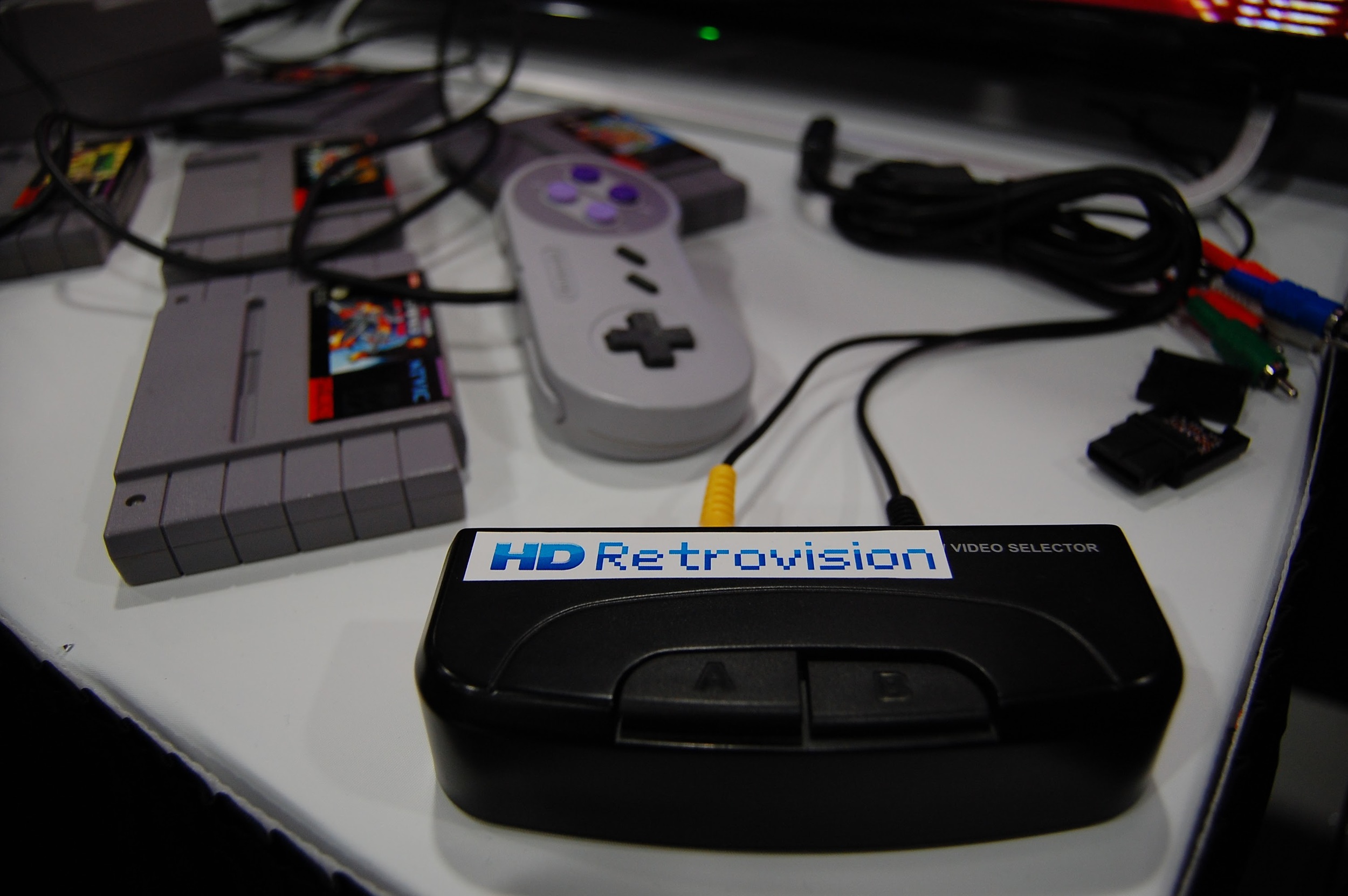
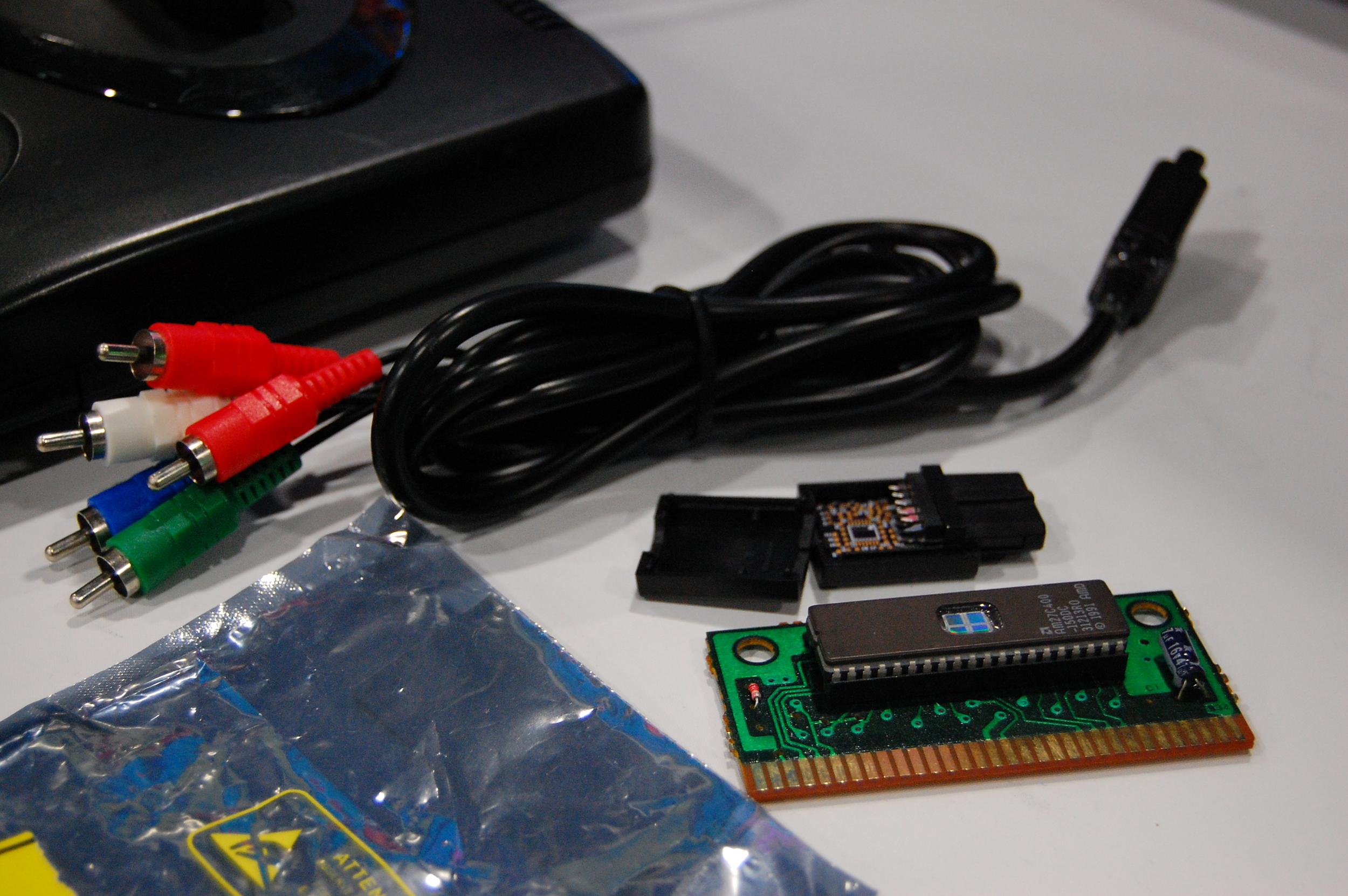
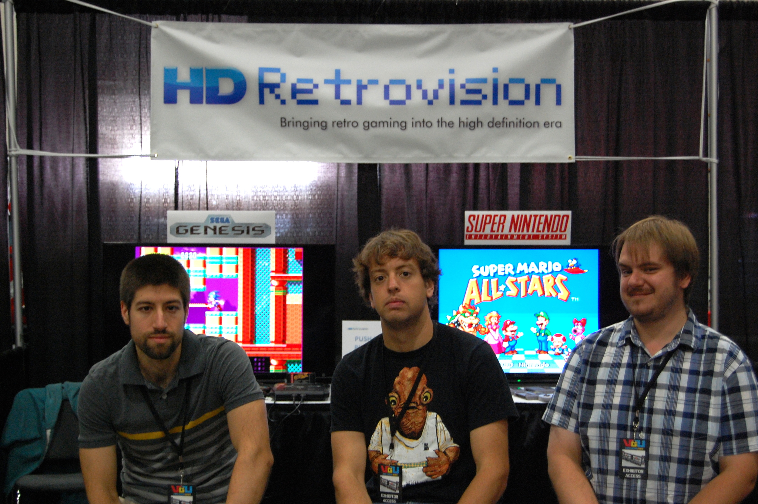
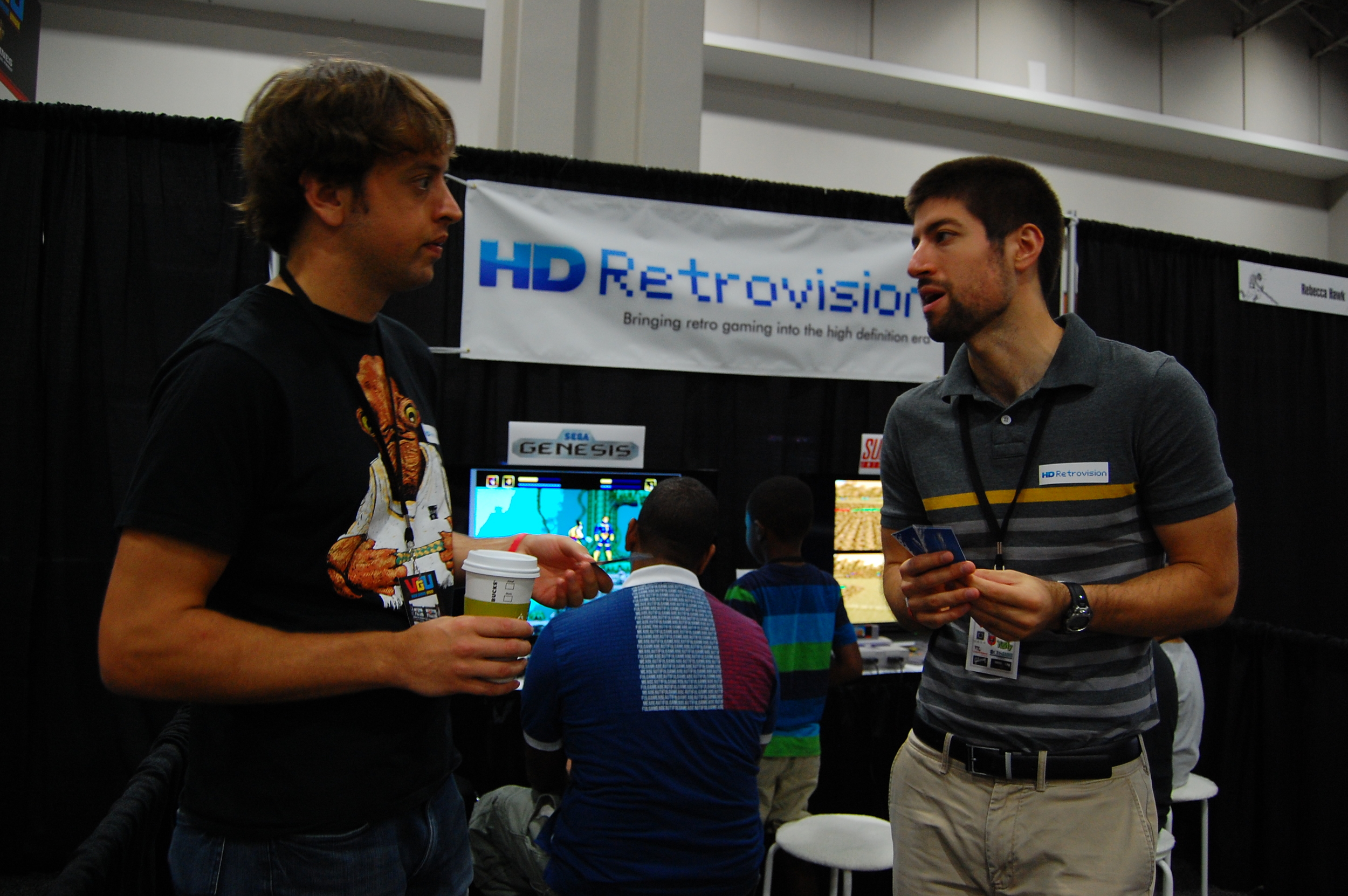
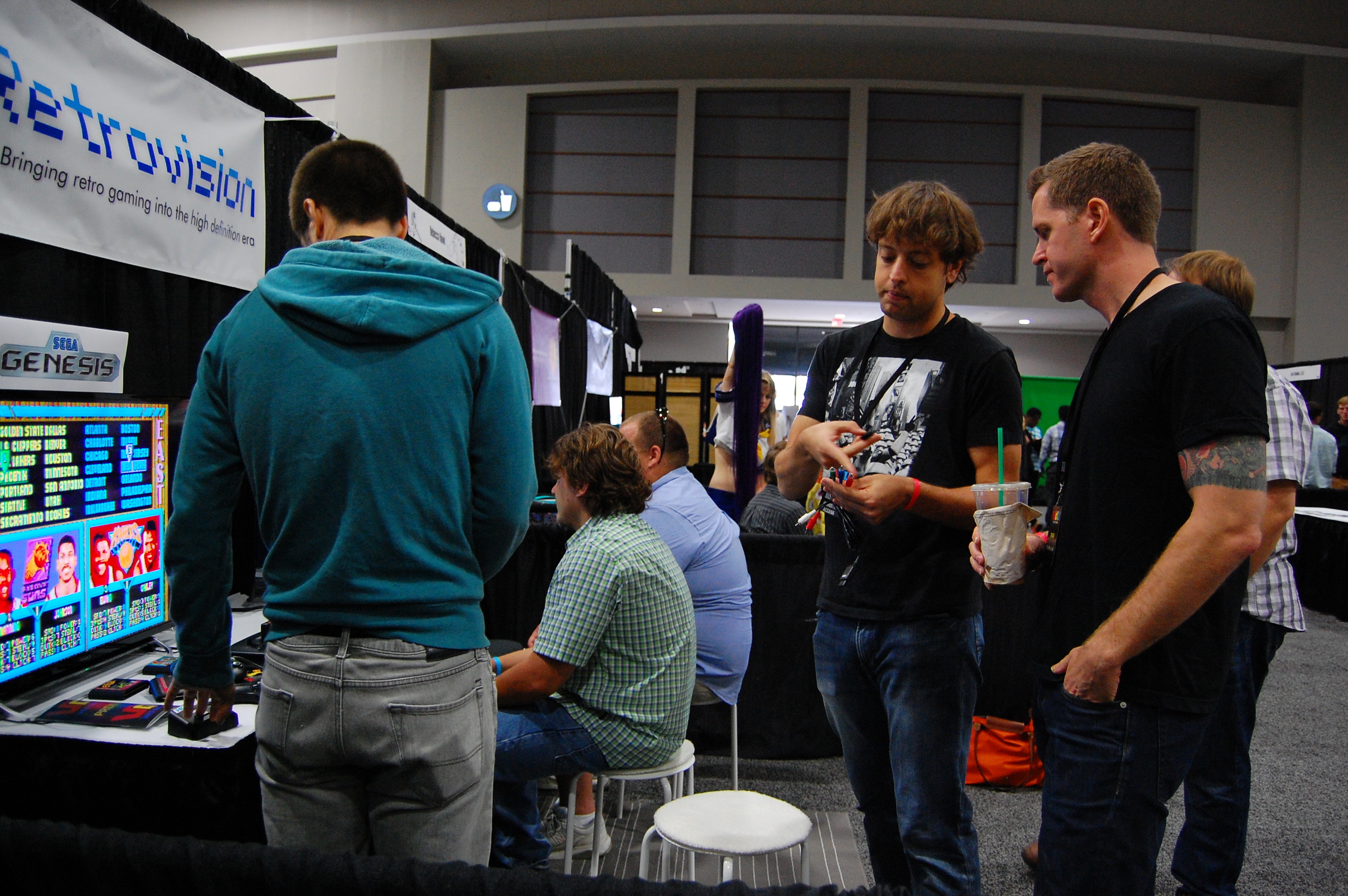
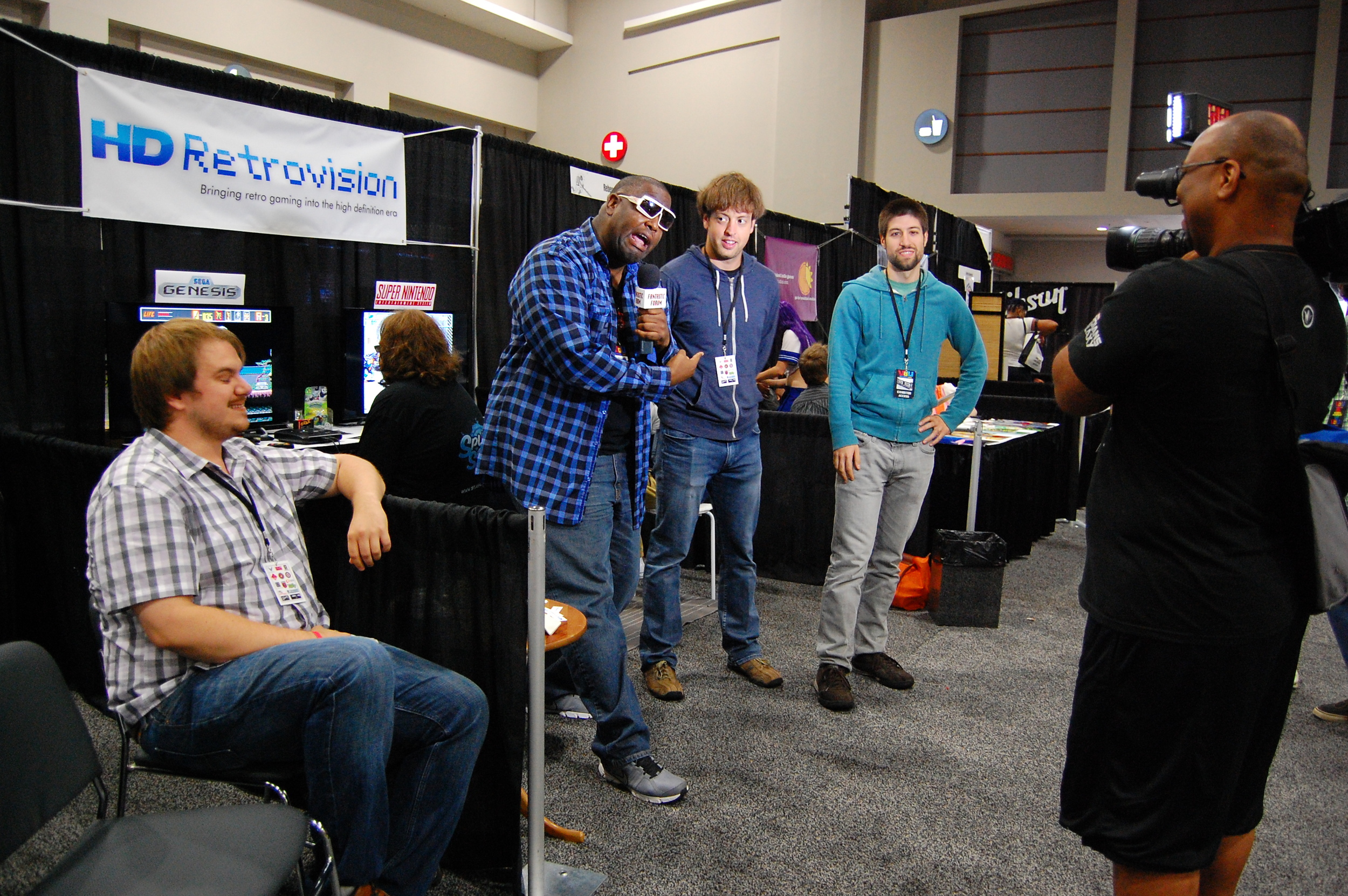
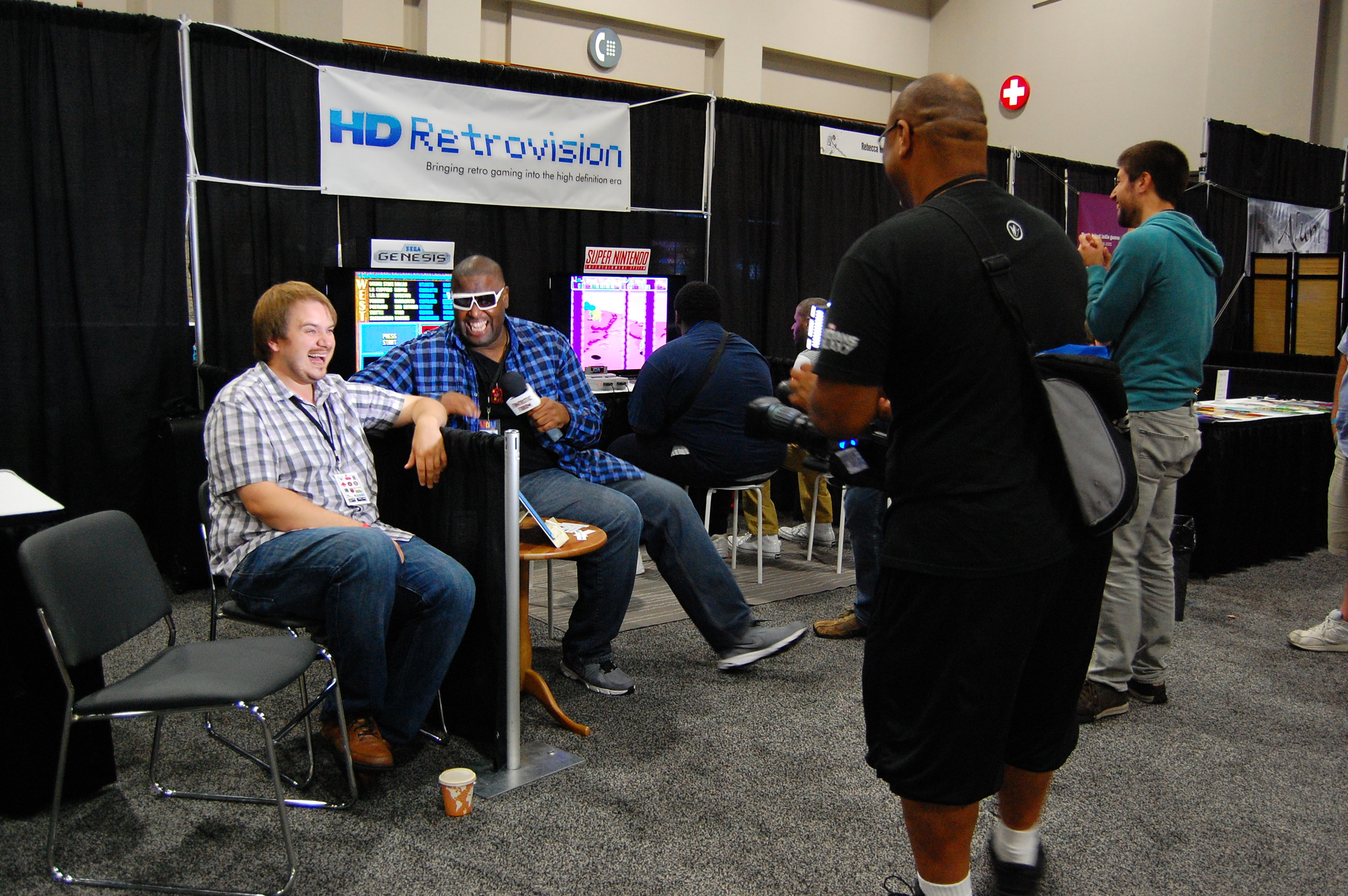
The heart of the controversy seems to be the fact that we call our company HD Retrovision. This name was chosen to reflect the fact that there is a gap between retro gaming and modern day HD Television sets. So why the issue with our name? Because our first set of products - component cables for SNES and Sega Genesis - output the standard definition video that is created by the console itself.

So we want to be perfectly clear: Our cables provide no High-Definition output or upscaling of any kind. 

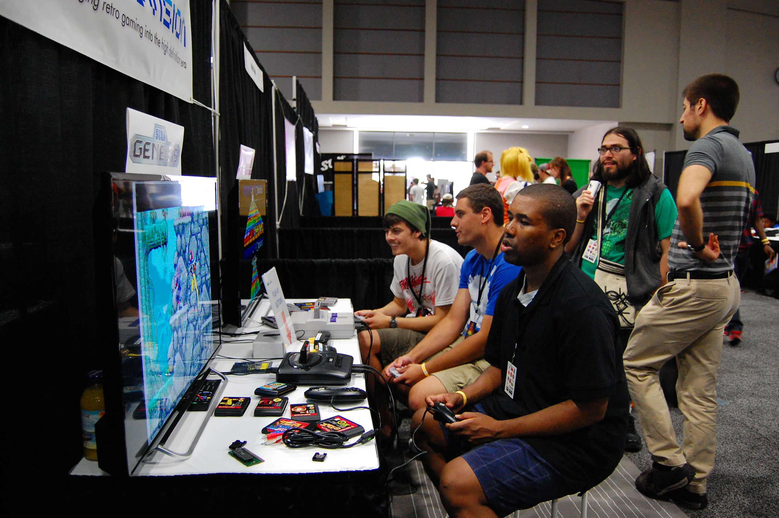
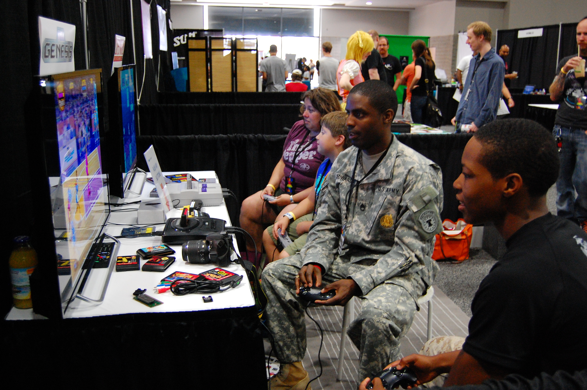
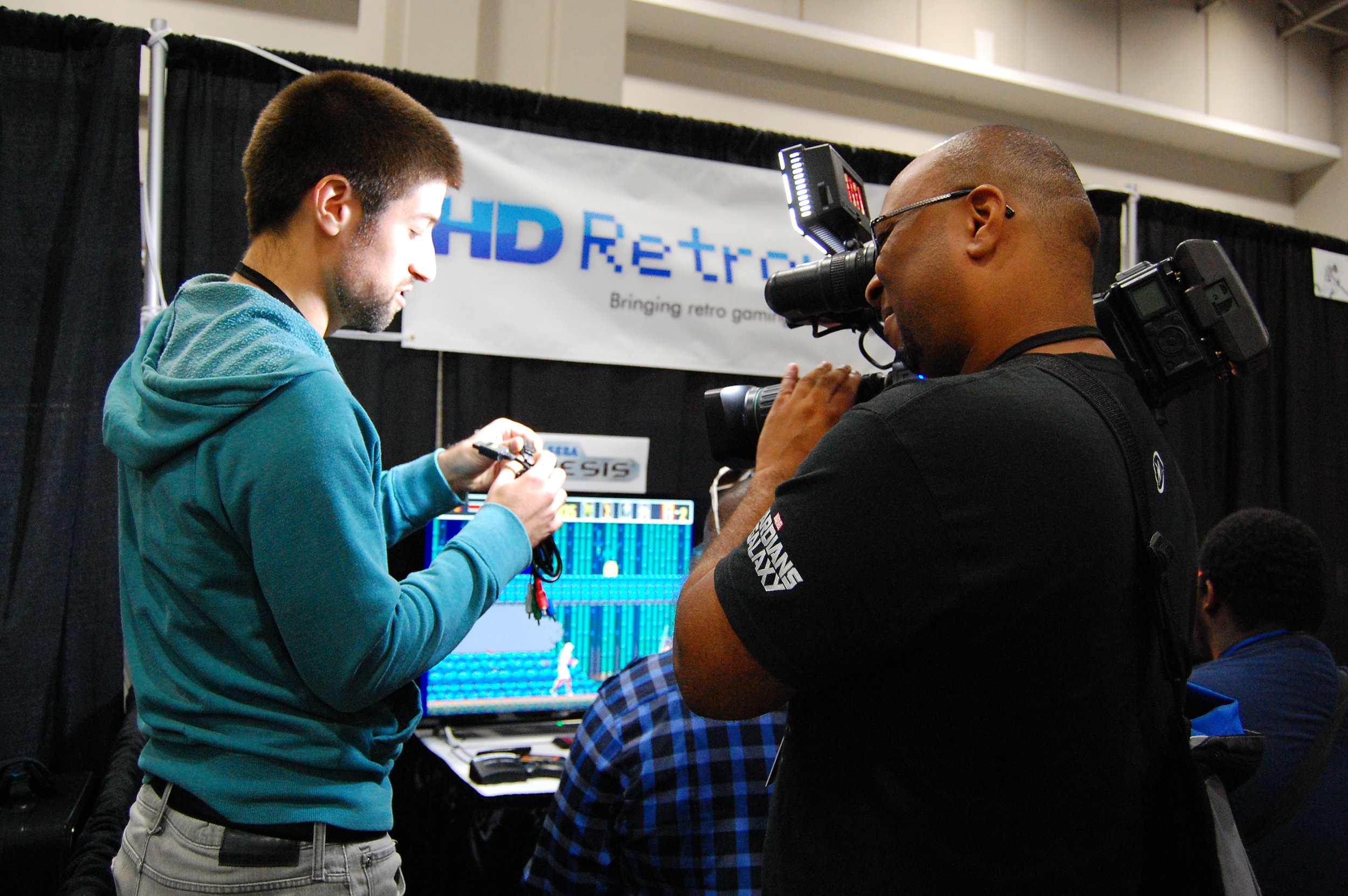
What we do provide is a clear, high quality picture from a simple plug-and-play cable that works with most HDTV sets. The quality you will see from them is a vast improvement over composite, and they provide a connectivity to modern TVs that S-Video does not. As we have noted elsewhere on the site, and others have pointed out, some HDTV sets do not play nice with 240p/288p video. For an in depth discussion on that topic, please see this page. That is a known issue that to the best of our knowledge appears to be going away with most newer television sets, but we are in development on a product that would resolve that issue as well.

As of right now, we're working toward adding more front-facing information to our entire online presence (website, YouTube, etc.) which explicitly state that these are not High Definition cables; including disclaimers on our various webpages and videos, additional information in our FAQ, and even re-rendering the trailer video to take out visuals that could be misleading.

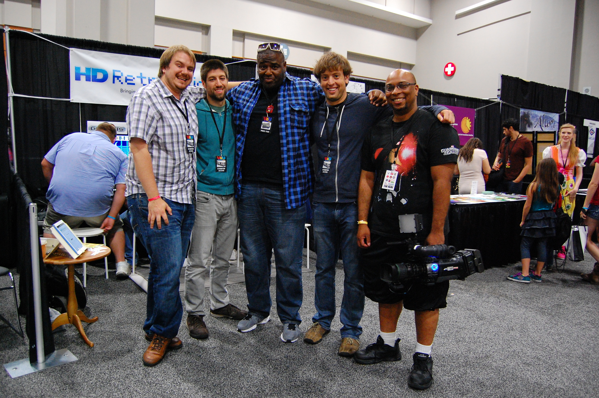
Thanks for your time. We appreciate all feedback provided to us by the community that helps us maintain our strict standards of integrity with our products.


Posted
AuthorNickolaus Mueller

We are proud to announce the launch of the "Free Stuff" section of our website.  There, we will post things produced during development that we believe will be of use to people in the retro gaming community.  The first item we're releasing is a ROM of our custom test software for the Sega Genesis.  We hope to continue adding items to the Free Stuff section as much as we can.  You can head over there right now to download the ROM, or continue reading below for a detailed explanation of why this piece of software exists in the first place.


If you're making something with the intent of having people buy it with their hard-earned money, it has to be done right.  We've mentioned a couple times that not all RGB outputs are created equal.  Different game consoles have different characteristics in their video signals.  Even the same consoles have been revised internally over their production lives, which can change these characteristics.  Hence, we need a way to measure and characterize these signals to produce a standard output conforming to CEA-770.2-D (similar to EBU N10-1998), which TVs are designed to accept.  Our solution was writing test cartridge software: our own "ROM" containing specific test patterns with the intent of running it on physical game consoles.  While the ROM is running, we can measure the signals with an oscilloscope and gather the information required in designing the proper circuit for that specific console.

Our first piece of test software was for the Sega Genesis.  A high quality and easy to use SDK, called the SGDK, made development for the Genesis/Megadrive much easier than how it was done back in the day by real game developers.  We initially made the software for measuring signals only, but it has since expanded to be used for other design aspects and also for use in the factory for testing and quality assurance of our cables.  I'd like to showcase the different test patterns and functions of our Genesis software:


Title Screen:

After powering on the console, you'll get our title screen sporting a Genesis-ized version of our logo along with other information.  It shows the screen size and scan mode that the Genesis uses at bootup.  There is a countdown timer of 5 seconds until the first test pattern gets displayed.  The purpose of the timer is that I need the software to be able to start without any input required from a controller.  However, if you do have a controller plugged into port 1, you can skip the 5 second countdown by simply pressing START.

splashscreen.png
 

100/0/100/0 Colorbar Pattern:

This is the main pattern used for testing and is the first test pattern in the cycle (launches after 5 seconds).  It allows us to do most of the required measuring of the RGB signals coming from the console.  The pattern consists of 8 vertical bars spaced evenly throughout the screen.  Each bar is one of the fully saturated colors found at the extremes of the RGB cube.  They are ordered from left to right in decreasing order of Luma (or "lightness" content).  Knowing what voltages the console spits out for these colors, enables us to properly scale the signals for a standardized output.

colorbars.png
 

Help Screen:

Pressing START on Controller 1 once the software has launched, brings you a screen full of instructions.  Only controller 1 is used.  A & B cycle through the different test patterns.  C toggles between non-interlace and interlace scanning for the Genesis video output (see below).  Pressing LEFT or RIGHT on the D-Pad performs the audio test (see below).  Current screen size and scan mode are displayed on this page, followed by version information.  The scan mode can be toggled by pressing C on this page.  The only other button that works in the help screen is START, which returns you to the test patterns.

helpscreen.png
 

Grayscale Bar Pattern:

This is similar to the colorbar pattern, except using the grayscale representation of the colorbar colors.  I found that color sub-carrier noise was easier to see on this type of pattern.  Some consoles exhibit this noise, and this pattern helps me with designing the correct filters to reduce the effect of the noise.

graybars.png
 

Solid White Screen:

This is simply a screen that is completely filled with white.  This pattern helps me measure the active video width of the console video signals.  With that information, I can determine the proper square-pixel representation to use when capturing video and screenshots.  This is probably an overlooked fact, but all of our videos and screenshots on our website have the correct aspect ratio.  What you see on your TV should match our uploaded content, in terms of the horizontal and vertical ratios.  A discussion of the concept of non-square pixels is a confusing property of analog video and is beyond the scope of this blog post.

white.png
 

Solid Magenta Screen:

This pattern is used for measuring the maximum power dissipated by our circuit.  When magenta is displayed, the amplifiers in our circuit draw the most current.  Since our circuit is powered from the console itself, we want to minimize the current sucked out of it.  Minimizing this current prevents stressing of the voltage regulator within the console.  Fortunately, our circuit is very power efficient, by design, and measures very minimal current draw out of the console.

magenta.png
 

Solid Blue Screen:

There is a synchronization pulse that needs to be extracted from the composite video signal and injected into the Y' signal of the Y'PbPr component video structure.  This is accomplished by "slicing" the composite video signal at a threshold where everything above it is discarded and everything else below is retained.  Blue is represented by a signal that gets very close to this threshold value, and can interfere with this slicing operation.  This pattern helps us verify the robustness of our slicing circuit.

blue.png
 

Solid Black Screen:

The North American version of the NTSC standard has a weird quirk that doesn't exists in PAL standards and in the Japanese version of NTSC.  "Blanking Level" is the voltage at which the video is not active.  "Black Level" is the voltage of the color black when the video is active.  In PAL and NTSC-J, these levels are equivalent.  But in NTSC-M (North America), black level is slightly higher than the blanking level, by about 54mV.  This test pattern let's me see where the console decides to put black in relation to the blanking level.  So far, every North American gaming console I have tested keeps the two levels equivalent, which means they all follow the Japanese NTSC-J standard.

black.png
 

Scanning Mode:

Pressing C toggles between non-interlace and interlace scanning for the Genesis video output.  A notification displays on the screen telling you which mode you just changed to.  You can go to the help screen to see the current mode.  Normally, these older game consoles and computers output a non-interlaced (progressive) signal.  The Genesis's capability of interlaced scanning is a little known fact hidden at the depths of the internet.  The most prominent example of the use of interlaced scanning on the Genesis is the Versus mode in Sonic 2.  Anyway, the main purpose of having control of switching the scan mode is to test a future product we will be working on.  We also wanted to verify that the console didn't change anything in terms of video output level while it was scanning in a different mode.

scanmode.png
 

Audio Test:

Pressing LEFT or RIGHT on the D-Pad produces a sound effect in the respective audio channel.  A notification displays on the screen informing you which channel should be playing.  The main purpose of this test is to make sure the audio is wired up properly within the cable after it is assembled.  This is exclusively a test to be done in the factory during production, or when engineering units are assembled.


That's pretty much it.  We might add more tests in the future, if needed.  We have a SNES version of this software, but it's not currently ready for public release.  When it is ready, we will post it on our "Free Stuff" page.  If you have any questions or suggestions, please feel free to contact us via the contact page.  As always, we appreciate your support.  Thank you.

-Ste


Posted
AuthorSte Kulov

Following up on some of the links to our webpage from various message boards and forums, we have noticed that some people have made comments that they were unable to tell the difference between our cable and composite video. That falls contrary to what we have heard from people who have seen live demos of the cable, both at VGU Con and from those with engineering prototypes. As such, we would like to make sure the difference that our cables make is accurately conveyed through PNG images and Youtube videos. 

People are able to clearly see the difference in quality for the Sega Genesis cables. This is due to the fact that the hardware converting the video into a composite signal on the Genesis is worse than on the SNES, so our cables make that much bigger of an improvement. Here's a zoom-in on NBA Jam for comparison.

The difference in quality here is obvious. Words are legible, color striping disappears and player likenesses and the logo are sharper when using the HD Retrovision component video cables. We see similar gains in visual quality in Streets of Rage below.

Now, if one goes from looking at Sega Genesis comparisons to SNES comparisons, it certainly might appear at first glance that the differences between composite and component video have disappeared. Or if one watches the SNES comparison video on a smaller screen, or without expanding the player to full screen and making sure HD mode is on, it again is definitely possible to miss some of the differences. And we're not going to tell you "Trust us, it's there." Instead, let's have a look at some zoom-ins from the SNES.

To begin with, here is a comparison from Mario Kart, where the differences are most obvious in the borders between mountain and sky, the text at the bottom, and on the Luigi character. The composite video contains minor color striping, as well as jagged and blurrier edges. Not only does this look bad in still images, but the jagged edges tend not to move consistently from frame to frame, which causes an unpleasant wobbling/strobing effect.

mariokart_1_bad.png

Here's another cut from Mario Kart, this time at the character select screen that really shows the jagged edge problem caused by using composite video. 

mariokart_2_good.png

To show we're not picking on poor old Mario Kart, here's a snippit from Super Mario World.

marioworld_bad.png
marioworld_good.png

Once again, the jagged edges are readily apparent, which in the case of the numbers causes them to be rendered with the wrong color more often than not.  As with the Sega Genesis, the video quality resulting from our component video cables is superior to composite video. And remember, when these games are played on large HDTVs, these differences will be much more noticeable than on most computer monitors.

We hope this post helps out those who were having trouble noticing the difference in the comparison videos or images on the other pages of the website. As an image processing engineer by training who has published papers with comparisons like this, I really should have done something like this sooner. Here at HD Retrovision, we're committed to making really cool products that work well and do what we claim that they do. We're also passionate about being open and honest with our work so that people can make informed decisions before they buy. So please, don't hesitate to send us any questions you might have!

- Nick


Posted
AuthorNickolaus Mueller

A common question we were asked during our time at VGU was how our cables worked. The actual implementation is somewhat complicated, but the concept is quite simple and can easily be understood by all.

Several consoles released in the 80's and 90's had proprietary connectors for the audio/video outputs.  If you were like me at the time, you got frustrated with these things. I know I was relieved when my launch Playstation 1 provided discrete A/V connections so I wouldn't have to deal with Sony's special connector.  It turns out that these seemingly annoying A/V connectors contained more than just the standard composite video (yellow) and stereo audio (white/red) we were used to.  In some cases, there were pins on those connectors which provided an s-video signal for improved picture quality on TVs with such a connection.  And that's it, right?  Well, yes, it was for us living in North America.  But out in Europe, all this was a sideshow to what was actually possible.

comp_svid.jpg

To understand the following, you need to be familiar with a very simple concept.  A display, such as a TV, shows an image by combining light in red, green, and blue (RGB) components.  A source, such as a camera, takes light in and splits it up into its RGB light components.  A different type of source, such as a computer graphics system, generates RGB signals directly instead of capturing them.  For optimal quality, you want this path from source to display to be as direct as possible.  Any deviations from this path can result in artifacts and visible errors on the display.  For example, to create composite video, the RGB needs to be heavily processed and combined into a single video signal. The processes involved in combining and then separating the video back into RGB causes a major deviation in the ideal path, hence the sub par quality achieved with using composite video.  The following diagram attempts to visualize this detour that composite video takes in relation to a direct RGB connection.

source_display_rgb.png

Back to the consoles.  Almost all of those funky A/V connectors had pins containing the raw RGB video generated by the graphics system of the console.  And in Europe, TVs have special inputs that can accept and display those signals.  They did this through a special connector on the television called SCART.  The connector was very large with many pins and incorporated several features to simplify A/V equipment connections.  Think of it as the analog precursor to the digital HDMI connection we are all familiar with these days.  With a special cable that connects the console RGB pins to the SCART connector, you can achieve an almost perfect source-to-display connection.

SCART.jpg

For us in North America (and several other parts of the world), we never had TVs that could accept these raw RGB signals.  But what about those red, green, and blue colored RCA jacks commonly found on our TVs?  Although physically colored that way, those are not RGB inputs, but they are very close.  YPbPr (or "component") video is only a simple, reversible transformation away from RGB.  So the idea is to perform the transformation for the purpose of using a compatible input on the TV.  Then, the TV will undo the transformation to recover the RGB and display it.  Below is one page of my engineering notebook which begins to explain the theory behind our product.  The diagram on top of the page illustrates the concept I've just explained.

ypbpr_concept.jpg

Some people say that you're just as good in getting an RGB SCART to YPbPr conversion box.  Disregarding the hassle and cost involved in dealing with conversion boxes, I still don't believe this is true.  We've spent lots of time here at HQ researching the RGB video signals coming out of both the SNES and Genesis consoles.  By using custom test software, the signals were accurately measured and we've determined that these consoles are not properly designed to follow any particular standard.  These video signals can be too dark, too bright, have slanted lines (field tilt), and contain unwanted noise.  These problems are compensated for within our cables. Think of our cables not only as simple plug-and-play conversion devices, but also as "signal conditioners" to achieve the best possible output from your consoles.

Like always, if you have any questions, please feel free to contact us via the contact page.  Also let us know if you like these more technical blog posts and if we should do more of them.

Posted
AuthorSte Kulov