First, an update on the existing product line. We've been low on / out of stock for many of our products for awhile, but the factory just finished up production on everything except Genesis and SNES cables. That shipment is headed our way next week. Genesis and SNES cables are still a few weeks out from wrapping up, as we just sent over to them the artwork for the new boxes they'll be shipping in, similar to our PS2 and Wii cables.

At long last, we're on the final leg of the Dreamcast journey! It took nearly 8 weeks from design file submission, but we finally received a quote from the factory. As of early December, we submitted the purchase order for the first production run of cables. Current goals for timelines are Q1 2020 to receive and approve production samples, and Q2 2020 for completion of the first batch. In the meantime, we are wrapping up design and documentation of the production test fixture for use in the factory. This is being done in parallel with the tooling and sample production, so we're not holding anything up as we work to complete it.

We'll be gradually shifting resources over to HDMI development as we move into the new year. We're hoping to demo something very cool at a convention in 2020. More info on that when we can faithfully commit to something.

Posted
AuthorNickolaus Mueller

In Part 1 of this series, I went over the historical background of CSYNC, including its purpose and how it is intended to be generated and then subsequently used for conveying television timing information. Within that description, I highlighted some key properties of the 480i CSYNC waveform and how that translates over to creating various 240p “flavors”. Since the advent of TV, personal computing and other applications have borrowed ideas from the engineering principles initially set forth in the complex design of television’s CSYNC structure. Along the way, a few of these principles have been ignored or overlooked to justify simpler solutions. Therefore, there are extremely common implementations from those early PCs days which have propagated throughout the decades and are thought to be “standardized” or “correct”. In this Part 2, I will cover the two most commonly used methods to form a CSYNC output from existing HSYNC and VSYNC signals, and why they can cause issues with equipment trying to use this resultant signal. Unless noted otherwise, we will be mainly working with the “Cookies & Cream” flavor of 240p (see Part 1) when discussing the sync waveforms.

AND Logic

There are tons of various flavors of this type of method, and they might not necessarily show up as an AND logic gate symbol (like the one shown above) in a schematic. For example, it could be an OR gate with input polarities flipped or a set of discrete components (diodes, resistors, transistors, etc.) implementing the logic in some approximated way. However, the fundamental principle is the same. The idea here is for CSYNC to normally push out the HSYNC information, but when VSYNC becomes active it completely overrides the HSYNC. An example of the ideal input/output waveforms passing through this type of logic is shown below.

If this CSYNC waveform looks familiar, it’s because it’s very similar to the first step (Step A) in deriving the correct 480i CSYNC as described in Part 1. It makes sense because this is the first logical step in trying to combine the two types of syncing information into one signal. Therefore the problem that this naive implementation causes is the same as was described in Part 1: the HSYNC information is lost during VSYNC and the display device will lose horizontal lock…..unless it has a mechanism which expects this scenario and can avoid it or correct for it. The 2nd part of the previous statement is key here and provides a justification for this method to be used in the first place. Many direct analog systems found in older computer CRTs are simply more tolerant, by their very operational nature, to missing a few HSYNC pulses while the electron gun is off-screen. They’ll lose sync briefly while off-screen and either recover completely before active video starts again or take slightly longer causing only minor distortion/tearing at the top of the screen. However. more modern systems are based on something called a digital phase-locked-loop (or PLL for short), which can cause much more severe problems for the end-user when used with a wonky CSYNC input.

An extremely rough description of a PLL would be a device that generates an internal signal, locks onto an external reference signal, and compares the two to create a new version of that internal signal that’s in phase relationship with the external reference. In a typical modern system, the PLL operates on HSYNC (sometimes called LLPLL for “line-locked” PLL) and assumes this incoming signal is consistent up to a certain point. This certain point would be the PLL’s “lock-in range” or “hold-in range” [NOTE: these ranges are somewhat different, but assume for now they are the same]. When designing a PLL, the engineers have to set this window and there are trade-offs involved. If they set the lock/hold range too wide, then the PLL can take too long to lock and/or the output signal can drift around very easily resulting in an unstable system. Set it too narrow, and the PLL will lose lock easily for input signals with even the slightest of flaws. If you’ve ever experienced a modern flat screen HDTV display a black screen or have its picture flashing on/off quickly, then you are witnessing its PLL rapidly switching from locked to unlocked status. This is because a modern video system will completely disable its video output when the PLL is reporting that it is not in its locked state. Many video decoder (video ADC) chips have a feature called “coast” which can tell the PLL to ignore the reference input signal for a certain amount of time and continue to output its own internally generated HSYNC during that time. If this coast time is short enough, then the internally generated HSYNC won’t drift off too much before the coast period is over, when it would then re-lock onto the reference and begin correcting itself again. Coasting is commonly used in well-designed video PLLs to solve the problem of bad or out-of-spec CSYNC inputs. In the specific case of dealing with a CSYNC created from AND logic, the PLL will generate its own HSYNC pulses during the VSYNC portion to completely eliminate the missing pulses problem, unbeknownst to the user.

If you notice I did not mention interlacing here, where the HSYNC pulses near and around VSYNC are extremely vital in making an interlaced system work. Therefore this type of psuedo-CSYNC creation method is more suited for progressive video, which is why you find it used in older computing and arcade systems. For example, here is an oscilloscope plot from a Sega Master System (Model 1) which shows that this version of the SMS video processor (VDP) implements the CSYNC via AND logic before spitting it out to the world. [NOTE: there is a slight glitch at the beginning of the VSYNC portion, which will be addressed later in this article.]

[Top] CSYNC from a Sega Master System (Model 1)[Bottom] Zoomed-in version of the top

[Top] CSYNC from a Sega Master System (Model 1)

[Bottom] Zoomed-in version of the top

XNOR Logic

The most commonly used method for generating CSYNC is via XNOR (inverted-exclusive-OR) logic. Again, you might find this implemented slightly differently, such as an XOR gate (XNOR without the inverting part) along with swapped input polarities on one or both of the incoming HSYNC and VSYNC signals. Anyway, this method attempts to resolve the “dead period” of having no HSYNC pulses during the VSYNC portion as found when using AND logic. An example of the ideal input/output waveforms passing through this type of logic is shown below.

The problems associated with an XNOR-generated CSYNC are not as obvious as with the AND logic case. At a quick glance, it looks fine, so a more in-depth look is required while comparing it to a correctly generated CSYNC.

The main problem is that although there are pulses now in the VSYNC region, they are not in the correct position. A proper CSYNC has all its falling edges line up with the original HSYNC falling edges, and here they do not. Put another way, this violates the property established in Part 1 of requiring a consistent length of time between each falling edge throughout the entire CSYNC waveform. This can wreck havoc on the receiving device since there’s no way to tell a video system: “Hey, switch between using falling edges to rising edges just in this one window…..ummm but only when you get an XNOR generated CSYNC….how do you detect that??? I dunno, good luck!….oh and also figure out how to handle the missing edge at the beginning of that window.”

Just as before, we can consider the practical impact of such an error in the signal. Many CRT systems will be highly tolerant or immune to this just as in the AND logic case. Considering a modern system which relies on a PLL, this can cause the same or similar problems as in the AND case. A PLL with a well thought-out coast system will be able to ignore the incorrect pulses and regenerate its own. Fortunately, it can still be less of an issue compared to AND logic because even a PLL with no coasting ability might still be able to remain locked during the brief VSYNC section. This can happen if the PLL’s lock/hold range is set wide enough to still catch most of the falling edges of the misaligned pulses. An example of this possibility is shown below.

Therefore, XNOR logic is definitely a step above AND logic in nearly every imaginable scenario. However, there is an additional precaution to take when implementing an XNOR based system, which you don’t have to consider in the typical AND case. This is the property of an XNOR gate to generate glitches when both signals change state at the same time or very close to the same time. For example, when VSYNC transitions low the HSYNC also transitions low. It’s impossible for the transitions of both signals to happen at the exact same time, so depending on the properties of the device handling the logic and all the circuitry/wires leading up to that device you are likely to generate an extra very short pulse near those transitions. An example of this is shown below, taken from a Sega Genesis running in Master System mode which uses XNOR logic for its VDP’s legacy mode to generate and output the CSYNC signal. [NOTE: this signal does not match up exactly with the drawings above and this discrepancy will be covered a bit later in this article.]

[Top] CSYNC from a Sega Genesis running in Master System mode[Bottom] Zoomed-in version of the top

[Top] CSYNC from a Sega Genesis running in Master System mode

[Bottom] Zoomed-in version of the top

If the glitch at the beginning of VSYNC is long enough it could be seen as an extra falling edge and throw the receiving system off. One way to combat this is to filter out any possible transition glitches by following the XNOR gate with an RC circuit driving into a Schmitt trigger digital logic buffer as shown below. The idea here is to select RC values which would snuff out glitches under a certain maximum width for your particular XNOR implementation. Keep in mind there is a trade-off here since this method can skew the widths of the pulses you want to keep, so it’s only good for very short glitches.

A circuit simulation of the proposed deglitch filter for Sega Genesis’s legacy XNOR output. Components values were selected to suppress glitches of roughly 100ns or less in length.

A circuit simulation of the proposed deglitch filter for Sega Genesis’s legacy XNOR output. Components values were selected to suppress glitches of roughly 100ns or less in length.

Return to Your Positions

Much of the discussion above has an underlying assumption which needs to be addressed: the input HSYNC and VSYNC signals are ideal with proper positioning and widths. The first clue to this assumption not holding in practice is found in the Sega Master System oscilloscope plot in the first section where there is a glitch at the beginning of the VSYNC portion. This is caused by the Master System VDP using a VSYNC which is shifted by one HSYNC pulse-width to the right, before going into the AND gate. Because HSYNC is rising while VSYNC is falling in that region, there is a small period of time where both signals are high, causing the glitch. This glitch, if short enough, can be removed similar to how the XNOR glitches discussed above are removed. The Genesis running in Master System mode also uses the same shifted VSYNC for its XNOR operation and is the reason its oscilloscope plot doesn’t match the ideal waveforms either. Keep in mind that even if a non-shifted VSYNC was used, it wouldn’t change the fact that transition glitches are generated since this phenomena is inherent to using XNOR logic when two signals are simultaneously changing state. Only the position of the glitches would change.

There are more severe cases where the input signal structure is not close enough to ideal to be somewhat usable after combined together using simple logic gates. The most common real-life example I can think of is with the TurboGrafx-16 (or PC Engine). The expansion port has the raw HSYNC and VSYNC available as pins on this connector. The first problem is that the HSYNC pulse is way too wide for the format it’s trying to represent (240p/480i), almost by a factor of 2.5x. The second is how the VSYNC alignment is off by a few microseconds, which when using either AND logic or XNOR logic for generation results in glitches that are much too wide to be removed. In fact, a naive implementation of CSYNC using XNOR logic on these two input signals is what caused many compatibility issues with the first revisions of the Super SD System 3 (SSDS3) from TerraOnion. Subsequent revisions used the already combined CSYNC available from the expansion connector which, although not 100% correct, is much more reliable.

[Left-half] HSYNC (blue) & VSYNC (yellow) on the TurboGrafx-16 expansion port along with a direct XNOR combination of them (violet).[Right-half] Internally generated CSYNC (violet) from the TurboGrafx-16’s video processor along with the same exp…

[Left-half] HSYNC (blue) & VSYNC (yellow) on the TurboGrafx-16 expansion port along with a direct XNOR combination of them (violet).

[Right-half] Internally generated CSYNC (violet) from the TurboGrafx-16’s video processor along with the same expansion port HSYNC (blue) & VSYNC (yellow) for comparison. Notice the smaller pulse widths and the lack of glitches. This looks to be created from a completely different set of HSYNC & VSYNC found only within the video processor, which were XNOR-ed together and then deglitched.

If it’s in a datasheet, it’s GOTTA be true!

Having laid out most of the issues with them, why are methods such as AND or XNOR so common? I mean, nearly all the information you find on the internet points to either one of these two logic systems being THE WAY to perform this task. You even have block diagrams from well-known IC manufacturers mentioning XNOR for their internal CSYNC creation.

Snip from the AD724 Video Encoder datasheet from Analog Devices showing XNOR logic for CSYNC creation. This is misleading since, if you read further into the datasheet, the XNOR block shown here is only a small portion of the decoding logic used to …

Snip from the AD724 Video Encoder datasheet from Analog Devices showing XNOR logic for CSYNC creation. This is misleading since, if you read further into the datasheet, the XNOR block shown here is only a small portion of the decoding logic used to generate the correct CSYNC patterns within the final Composite Video and S-Video outputs.

Although I think much of it is due to ignorance and an unwillingness to fully understand the nuances of analog video, I have to concede that the main reason these methods are still used is due to how they have the ability to work with several various input formats. So in a device which can accept many different HSYNC/VSYNC input formats, using something like an AND gate would be a very cost-effective way to have it “mostly” work across a wide range of inputs. This is especially true in the XNOR case and if you consider the VESA Display Monitor Timings (DMT) used for systems with VGA connectors. There are various VESA formats which deviate from the typical active-low sync practice, and can either have one or both of HSYNC/VSYNC be active-high instead. The XNOR method can produce some kind of a CSYNC output in all four of the possible polarity cases for HSYNC/VSYNC.

Snip from the VESA DMT document showing the differing sync polarities for 1280x800 @ 60Hz

Snip from the VESA DMT document showing the differing sync polarities for 1280x800 @ 60Hz

The Cost of Doing Good Business

There are methods which attempt to correct CSYNC after it is generated from either AND or XNOR logic. TB476 is an Application Note from Renesas Electronics which details a system for doing this using ICs they manufacture. The final circuit is very large and complex, and it can’t universally correct for every type of format, especially any type of interlaced content. It’s still worth a read, since it’s one of the rare resources found on the internet that actually acknowledges and corroborates that these AND/XNOR based CSYNC generators cause problems.

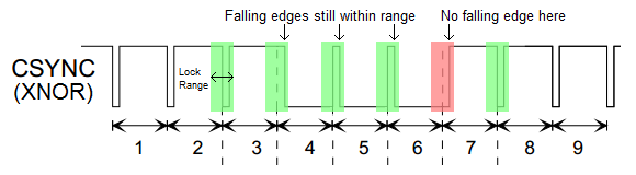
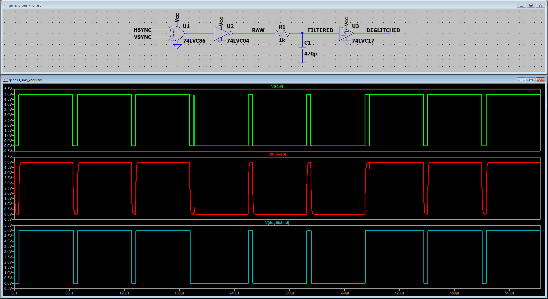
For systems/devices that are only expecting and targeting one type of video format, I believe it’s worth implementing the extra time, resources, and effort to make sure the end-user has a trouble-free experience by generating a proper CSYNC signal. It’s not worth the risk relying on auxiliary safetynets, such as PLL coasting or wide lock/hold ranges, that may or may not be engineered into a receiving device. Even in multi-format systems which are already generating the HSYNC and VSYNC in the first place, you should be able to additionally generate a correct CSYNC with minimal extra effort and cost instead of opting for an AND/XNOR gate. This is especially true if you have to deal with realigning pulses prior to the logic gate and then filtering out glitches on the output, which is already a bunch of additional work in the first place. Lastly, it’s worth iterating once again that none of the methods discussed in this article can handle interlaced formats in a manner that even begins to approach a reasonable level of reliability.

Summary

The main takeaways from Part 2 are as follows:

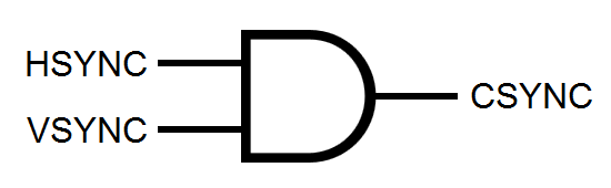
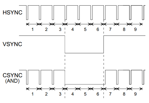
1.) AND logic is the most basic form of CSYNC generation, and it was used commonly in early progressive-based video systems.

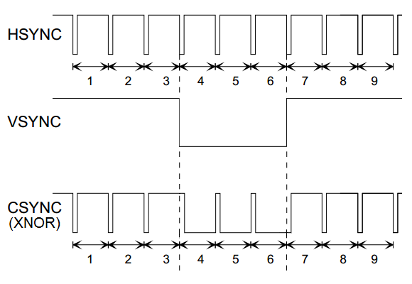
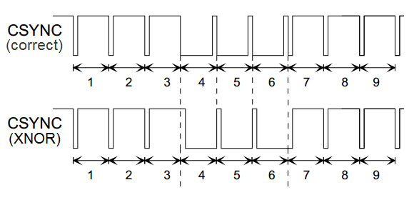
2.) XNOR logic is a step above AND logic in terms of reliability, as long as you mitigate the creation of transition glitches.

3.) For either of these methods to work reasonably well in enough scenarios, proper widths and positional alignment are required on the input HSYNC and VSYNC signals.

4.) These two simple logic gate methods have a unique benefit where they can be used effectively in a universal system dealing with many possible input formats.

5.) Fixing CSYNC errors after generation is very costly, unreliable, and non-universal. It’s also very difficult to do for interlaced systems.

In the upcoming Part 3 of this series, I’ll try to finally tackle proper CSYNC generation. If you are familiar with digital logic, both of the methods discussed above are types of “combinational logic”. The 2nd type of logic used in digital systems is known as “sequential logic”, and it’s what we need to use to engineer a correct CSYNC output.

Posted
AuthorSte Kulov

- We have a new product out for sale! Wii YPbPr component cables can now be purchased via our Amazon store. You may notice that they also come in a shiny new box with a bunch of boring warnings and symbols plastered all over it. We'll eventually port all our products over to new snazzy packaging, but in the near future it will just be the PS2 and Wii cables. Current Wii inventory may be a bit patchy as we only air shipped in a tiny batch, while the rest are due to arrive via ocean freight sometime in July.

- The next batch of Genesis YPbPr cables has landed! We'll start pushing these out to our distributors (Castlemania Games, RetroStuff Canada) in the coming week or so. Just like with SNES YPbPr cables, these will not be available on our Amazon store, so make sure you are set up to get the latest information from your preferred distributor(s).

- PlayStation 2, M-M RCA, and M-F extension YPbPr cables just wrapped up at the factory and are due to head our way via ocean freight soon. We're anticipating a mid-summer date for the full restock of those, but we air shipped ourselves a small batch of PS2 cables to get Amazon going in the meantime. Those should be found at the same Amazon link in about a week or so, assuming no issues are found during our standard QA check.

- Dreamcast development is chugging along and the end of the design phase is finally in sight. Last month, we resolved the last of the 21 known issues/bugs with the prototype circuit, and the overall results are looking fantastic on the workbench. We are now waiting for the factory to finishing sorting out a bunch of their overmolding requirements before we throw down a final circuit board layout. They're being slow about giving complete and thorough information about this, so in the meantime we are working on the design verification procedures and also the test equipment which needs to be in place for mass production.

Be sure to check us out on Twitter if you want more frequent updates!

That's all for now, folks!

Posted
AuthorNickolaus Mueller

One of the most common questions we get asked during The Retro Roundtable podcast is “What is the proper way to generate CSYNC from HSYNC and VSYNC?”. People understandably ask this because we’ve mentioned several times that nearly all implementations of this process are incorrect. The question is typically asked with the expectation that it can be quickly answered. I mean, if we’re able to so easily point out improper implementations, then shouldn’t we be able to just as easily explain the correct implementation? Unfortunately, this isn’t true with nuanced topics such as this one. Therefore, I’m going to try my best and explain this subject here in detail so it can be properly documented and easily referenced. I’ve determined that this information would be best presented and understood when split into 3 separate parts. Let’s begin with the first part which covers what CSYNC is and why it exists in the first place. This background is necessary for understanding the difficulties that arise with the proper creation of CSYNC from discrete HSYNC & VSYNC.

Defining “Sync”

Sync is short for synchronization, and refers to how a video system needs to be “locked on” or, in simpler terms, stabilized. CSYNC, or composite sync, can be described as a combined version of the HSYNC and VSYNC signals. Since CSYNC is defined by those two sub-components, we need to first understand them. HSYNC is horizontal sync and VSYNC is vertical sync. A video system’s end goal is to display an image on a 2D screen, where the two dimensions are horizontal and vertical. Therefore, HSYNC keeps the horizontal axis (each line) stable by defining the horizontal reference point, while VSYNC does the same thing for the vertical axis (each frame or field). Both of these references are required for the image to be properly reconstituted on a display device. An example showing the HSYNC and VSYNC waveforms for 60Hz standard definition video is shown below. As discussed in our Sync Jitter article, the falling edges of these waveforms represent the desired reference points (line start for HSYNC; field start for VSYNC). Note that in this example there are two unique fields which keep alternating between each other. The second field of each two-field sequence begins in between two lines and is used to achieve interlacing* as detailed further below in this article.

*NOTE: I’m not going to get into the whole concept of interlacing and why it was chosen for television broadcasting. The only thing required to know is how interlacing affects the structure of HSYNC & VSYNC and the encoding of CSYNC.

HSYNC and VSYNC waveforms representing 60Hz standard definition video. Line numbers are labeled as are the two unique fields required for interlacing.

HSYNC and VSYNC waveforms representing 60Hz standard definition video. Line numbers are labeled as are the two unique fields required for interlacing.

When monochrome (black&white) television broadcasting (as defined by RS-170/EIA-170) was first introduced in North America, a scheme needed to be devised to combine (encode) all the required audio & video information into a single signal for transmission over the airwaves. One of the steps involved in achieving this was to convey the HSYNC and VSYNC information in a way such that it can be interpreted and utilized by the display device to make the final image. “Information” is very crucial to emphasize here. Video cameras and other video source equipment destined for TV* consumption do not explicitly generate separate HSYNC and VSYNC signals which are later combined into CSYNC via a separate circuit or procedure. The CSYNC signal is generated directly in a manner where the underlying HSYNC and VSYNC data can be inferred by the circuitry in the target device. The takeaway here is that the explicit HSYNC and VSYNC signals are only ever accessed at the display side.

*NOTE: This discussion focuses only within the context of television. The modern computing and PC space handles things differently, where HSYNC and VSYNC signals are explicitly generated and transmitted over a short distance to the display (e.g. VGA cables).

Generating a Practical CSYNC

The most straightforward way of doing this would be to simply widen the HSYNC pulse whenever VSYNC is active [section (A) in the figure below]. The main problem with this is that a display device loses HSYNC lock during this portion. The solution is to introduce a series of wide pulses which still have falling edges where HSYNC falling edges would occur [section (B) in the figure below]. In analog video terminology, these wide pulses are called “broad pulses” and the resulting small inverted pulses are called “serrated pulses”. This should be all that’s needed, but in order to effectively implement the interlacing scheme used by standard definition TV, we require one more tweak. Because the VSYNC is offset by half a line (i.e. halfway between HSYNCs), double-pulses at twice the HSYNC rate are introduced in the areas around and including VSYNC [section (C) in the figure below]. During the 3 line period prior to VSYNC, there exist 6 “pre-equalization” pulses. Similarly, during the 3 line period after VSYNC, there are 6 “post-equalization” pulses. Additionally, the width of these equalization pulses is half the width of the normal HSYNC pulses. The evolution of this concept along with the various waveforms are shown below.

Evolution in the design of a proper CSYNC signal for practical transmission and recovery:(A) = Naive direct logical combination of HSYNC and VSYNC(B) = Addition of broad/serrated pulses during VSYNC to keep HSYNC lock(C) = Addition of double-pulses …

Evolution in the design of a proper CSYNC signal for practical transmission and recovery:

(A) = Naive direct logical combination of HSYNC and VSYNC

(B) = Addition of broad/serrated pulses during VSYNC to keep HSYNC lock

(C) = Addition of double-pulses and shortened width for pre/post-equalization pulses to maintain interlacing

To validate the practicality of the finalized CSYNC waveform above, we can briefly examine simple examples* of how HSYNC & VSYNC can be recovered at the display side of the video system. Since this properly constructed CSYNC retains all of the original HSYNC’s falling edges, we can use those edges to trigger a monostable multivibrator (aka “one-shot”) to generate HSYNC pulses at their standard widths and at the correct locations. If required for a particular application, a second non-retriggerable one-shot, controlled by the same CSYNC input but with its output set just shy of the total line length (at about 95%), can be used to inhibit the output of the first one-shot in order to ignore the double-pulses during pre/post-equalization and VSYNC. For discrete VSYNC recovery from CSYNC, a simple two-stage RC integrator (filter) followed by an analog comparator set at a suitable threshold can be used to recover the wider VSYNC while ignoring all the shorter HSYNC pulses. An example circuit of this outlined VSYNC recovery method and its relevant waveforms are shown below.

*NOTE: These examples are highlighted and discussed for educational purposes only.

Simple RC integrator + analog comparator VSYNC recovery circuit.

Simple RC integrator + analog comparator VSYNC recovery circuit.

31 Flavors of 240p

The above CSYNC timing structures describe the 525-line 60Hz system (59.94Hz for color), or “480i” as it’s more commonly known today. 240p, in its most simple representation, is a slight variation on the above timing. Instead of drawing 262.5 lines in between each VSYNC edge to achieve interlacing, the idea is to have an integer number of lines which is needed for progressive scanning (the ‘p’ in 240p). There are two main ways of accomplishing this. Game consoles, retro computers, and various other devices are known to implement either one of these two types. You can either get rid of a half-line resulting in 262 lines, or add an additional half-line bumping you up to 263 lines. Regardless of which method is implemented, each field’s timing pattern now looks exactly the same, and the concept of first/second fields no longer applies. Therefore, the term “field” is dropped and the set of lines between each VSYNC edge is known as a frame. Because of all this, even more variations of 240p manifest themselves. The double-pulses no longer serve a practical purpose, so a common variation used by video equipment manufacturers is to remove them from the pre-equalization section, VSYNC broad/serrated pulse section, and post-equalization section. On top of that, some implementations choose to also increase the widths of the shorter pulses during pre/post-equalization back to the normal HSYNC pulse width.

As you can see, it starts to get quite messy once 240p comes into play. A handful of some different possible 240p flavors are shown below. Although there are many combinations of these slight variations, not one of them is documented within a video standard. However, within most implementations of 240p CSYNC the critical properties of the timing structure stay intact, increasing the likelihood that the signal can be properly recovered and interpreted by modern television receivers. These properties include (1) having 262 or 263 total lines per frame, (2) the length between each HSYNC edge being constant from line to line, and (3) the length between each VSYNC edge being constant from frame to frame. #1 is important because although analog CSYNC was never standardized, both 262-line and 263-line progressive video are standardized in the digital CEA-861 timing specifications used for HDMI. Therefore, a modern digital display at least has a defined target digital destination it can map an incoming analog CSYNC source onto. #2 and #3 are vital because PLLs (phase locked loops) are used to regenerate the pixel clock by locking onto consistently occurring HSYNC and VSYNC edges. Any peculiarity in the position of the edges can cause the PLLs to lose lock and result in a “no signal” message, a “mode not supported” message, or a flickering screen. #2 and #3 are so important that they also apply to any input format, and aren’t exclusive to 240p.

A handful of the many possibilities for 240p CSYNC. All the flavors shown here adhere to the 3 critical timing rules discussed above.

A handful of the many possibilities for 240p CSYNC. All the flavors shown here adhere to the 3 critical timing rules discussed above.


Summary

The main takeaways from Part 1 are as follows:

1.) CSYNC is typically generated directly, and not from a combination of existing HSYNC and VSYNC signals.

2.) Many properties for proper CSYNC were established specifically for interlaced television broadcasting applications. These properties are now standardized and need to be followed today even if the original technical reasons are no longer relevant.

3.) 240p CSYNC, due to its similarity to 480i, has many variations which can easily confuse display devices.

4.) Adhering to the outlined critical timing specifications as strictly as possible greatly increases the chances that no issues arise when decoding CSYNC signals, regardless of input format (i.e. 240p, 480i, 480p, etc.).

Stay tuned for Part 2 where I’ll describe common CSYNC implementations derived from explicit HSYNC & VSYNC signals which don’t quite cut the mustard. These implementations break one or more of the timing properties established above.

References

  1. Benson, Blair, and Jerry Whitaker. Television Engineering Handbook: Featuring HDTV Systems. 2nd ed., McGraw-Hill, 1992.

  2. Jack, Keith. Video Demystified: A Handbook for the Digital Engineer. 4th ed., Newnes, 2005.

  3. Poynton, Charles. Digital Video and HDTV: Algorithms and Interfaces. Morgan Kaufmann Publishers, 2003.

  4. Consumer Electronics Association. "CEA-861-D." A DTV Profile for Uncompressed High Speed Digital Interfaces, June 2006.

  5. Electronic Industries Association. "EIA-170." Electrical Performance Standards - Monochrome Television Studio Facilities, Nov. 1957.

  6. Society of Motion Picture and Television Engineers. "SMPTE 170M-2004." Composite Analog Video Signal - NTSC for Studio Applications, Nov. 2004.

Posted
AuthorSte Kulov

Salutations, fellow ghosts and goblins! It's been awhile. And though we're sure you haven't missed us, we just reached a point where we're able to give you a decent status update. Here we go:

First, the main reason we've been quieter than usual is due to the fact that we moved out of the basement/dining room and into an actual office/lab space. It was a lot of time and work setting this up, but it has already paid off in streamlining our new development projects and how we operate in general. Those new development projects, including the Dreamcast YPbPr cables, are still in progress. No further updates about those just yet, but the mailing list will get an update as soon as we have something significant to share.

OK, we do have one small update on new projects. As of last month we officially became a licensed HDMI® Adopter, which means we can now legally design, manufacturer, and sell products using HDMI® technology. We're excited to be one of the first companies in the retro gaming/computing arena to be allowed to do this.

The factory just wrapped up a production order that contains Genesis YPbPr cables, SNES YPbPr cables, PlayStation adapters, 5x RCA Male-to-Male cables, and 5x RCA Extension cables. These will soon be on their way via ocean freight, and will take the usual unpredictable amount of time to get here. We will not be reopening our store right away when they arrive. In order to continue making progress on new projects, our store will remain closed for awhile longer. However, you will be able to purchase from the new shipment of products through distributors such as CastleMania Games and Retrostuff.ca. Please visit their websites for information/updates about what stock they'll have and when. CastleMania may be doing a pre-order system soon -- check with them for details.

When we eventually do reopen our own store, we will only be offering shipping to domestic (USA) customers. Selling internationally adds too much complexity and risk for us, making it much harder to continue doing things other than running a store. International customers can still purchase through the aforementioned distributors.

Lastly, we placed a couple of our more basic products on Amazon.com for sale and distribution. Depending on how well these sell on Amazon, we might consider posting more products there in the future.

skeleton.jpeg

Have a very spooky October!

The terms HDMI and HDMI High-Definition Multimedia Interface, and the HDMI Logo are trademarks or registered trademarks of HDMI Licensing Administrator, Inc. LLC in the United States and other countries.

Posted
AuthorNickolaus Mueller