We thought we'd give everybody a little insight into our painfully long, but now concluded, journey of selecting a PlayStation A/V connector for our PS1 adapter.

Model 2 Genesis to PlayStation 1 Adapter (Prototype)
Chapter I: Bad Omens
The roots of this can be traced way back to July 2015, when I helped build FireBrandX a PS1 RGB JP-21 cable so that he could create XRGB-mini Framemeister profiles for PS1. His typical supplier for his cables were out of stock at the moment, so I offered to help. For this, I used an A/V connector I salvaged from a junky aftermarket PS2 YPbPr cable I got off eBay. After building the cable, I tried it out on a couple of PS1 consoles and noticed that on at least two of them, the fit was extremely tight, both on insertion and removal. I also tried fitting it in a couple PS2s, which didn't feel nearly as tight as the PS1s. Anyway, I informed him about this so he was aware, but it didn't affect his testing and he was only using it temporarily to create the profiles.
After getting my first taste of a poor A/V connector fit, I tried a bunch of different cables I had lying around. I noticed that the first no-name PS2 YPbPr cables I had ever bought several years prior fit way better than the newer ones I had on hand. There are two distinguishing features to the older 3rd party cable: (1) the plastic part of the connector has an oval indentation, and (2) the audio wires are held together by a piece of heat-shrink tubing instead of a plastic clip. Also worth mentioning, both the official Sony branded PS1 SCART and PS2 YPbPr cables I owned fit great without any issues.

Distinguishing features between "bad" fitting cable (left) and "good" fitting cable (right)

Official Sony PS2 YPbPr (left) and official Sony PS1 RGB SCART (right)
I bought a bunch of samples from various eBay vendors to see if I could find the better fitting version. After many failures, I got lucky with a seller in Canada. After confirming the sample was what I wanted, I asked the vendor for more information on where these were acquired from. He didn't know anything beyond that he's selling from the same batch he's had for years, so I instead purchased a box of about 20 pieces. The intention was to hold onto them in case we needed plenty of samples to send to future suppliers for a match. At this point in history, Nick and I were still intending to build our SNES & Genesis YPbPr cables in the USA, so we were dealing with Chinese suppliers directly.
Chapter 2: A Futile Search
Fast forward 6 months to January 2016, when we flew in to meet our newly hired contract manufacturer (CM) for our SNES & Genesis YPbPr cable project which was in the process of being transferred to production. While there, we gave them some A/V connector samples for Saturn, Neo Geo AES, and PlayStation. This included one "bad" PS1 connector and one "good" PS1 connector. Throughout 2016, we received various samples our CM acquired from overseas. Neo Geo was a one-and-done deal, while we rejected three Saturn samples before landing on one that worked. However, every PlayStation connector we received was of the "bad" fitting variety. We rejected several of these, and this prompted an analysis into why these fit worse than the "good" variant we were happy with.

Two incorrect Saturn connector samples (left) and one correct Saturn connector sample (right)
It turned out that the tension introduced by the displacement of the metal pins were the cause of the excess force required for insertion/removal. In the "good" variant, the pins had more room to move upward while they pressed up against the flat surface in the mating console connector. A closer analysis showed that the construction of the pins in the official Sony connectors were much different than either aftermarket version. Instead of a solid piece of metal being displaced, in the Sony connector the tips were bent and folded back to form a springy type of contact during mating. The problem with the solid non-springy types was that while they fit OK in composite video applications with only a few pins populated, the ones sold for RGB applications have all 12 pins populated, increasing the amount of tension significantly. We confirmed this suspicion by taking a tight fitting "bad" connector, clipping all the pins, and then seeing that the fit transformed from a death-grip into something that slipped in and out like butter. Regardless, after much reluctance we finally said "OK" to the poorly fitting connector (for now) since that's all they could find and we wanted to proceed with the project.

Solid pins (aftermarket) vs. springy pins (official Sony)
After finishing up signal measurements for Saturn and PlayStation, we were able to calculate internal resistor values and create technical drawings in February 2017 to send to our CM for quote. Based on our drawings, I made prototypes using the sample connectors to verify the electrical design. When testing out the PS1 adapter, I had so much trouble removing it from one PlayStation console that I elbowed some drywall (ouch!) with the excess force when it finally disengaged. This event, combined with other opinions from friends and colleagues, put us in a position where we were no longer comfortable with using this connector. Therefore, we put the PS1 adapter project on hold and asked our CM to take more time in locating something else.
During Spring 2017, our CM sent us a couple new connector samples. Although they were slightly different in construction, they still didn't fit any differently than the previous samples since they used the same solid non-springy pin design and didn't include excess room for the pins to easily displace upward. In parallel with this, I started buying every aftermarket PlayStation cable variant I could find which had all 12-pins populated. I wanted more data points to verify that everything being manufactured these days were all using the same tight-fitting connector variants. This unfortunately ended up being true, which meant that the better fitting variant we encountered a while back is an old design that is no longer "in print".
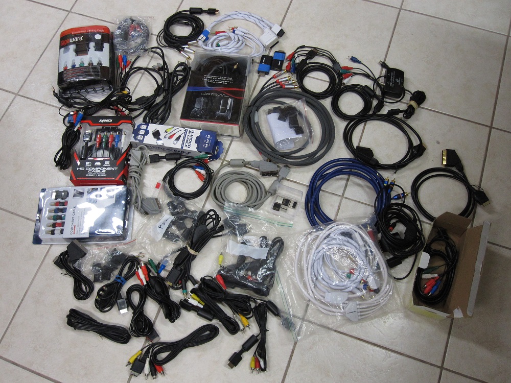
Contents of "the PS1 Box", i.e. various cable/connectors we tried
Chapter III: The Custom Connector Debacle
With all these roads leading to failure, in May 2017 we asked our CM if they could subcontract a supplier to spin us up a custom connector with springy pins like what the official Sony cables had. We bought and sent them a couple official Sony PS3 YPbPr cables to base the design off of. They asked around and finally found one factory which said they would do it for $(a large sum of money)....all in advance. Another caveat was that they first required us to specify hard numbers for the upper and lower limits of insertion/removal force, such that they could properly validate the design once completed. Because we were planning to eventually build PS2 YPbPr cables using this same connector, we were able to justify spending this kind of money upfront since this cost could be absorbed across more units. Up against a wall at this point, we agreed to proceed down this path and began figuring out min/max force specifications for insertion and removal.
We had never done this type of analysis before, and I actually got help from some mechanical engineers at my day-job. I purchased a force gauge which I estimated to be in the correct Newton range and prepped three different connectors for test:
A = Bad fitting aftermarket
B = Good fitting aftermarket
C = Official Sony from PS3 cable
We attached a PlayStation 1 console to a special table so it was properly held down and immovable. The force gauge came with a flat plate-looking thing for push (insertion) testing, and a hook for pull (removal) testing. The push was straightforward, but the pull required a small hack where we drilled holes in the connectors and attached thick zip-ties to form a feature for the hook to grab onto. The force gauge had a RS-232 serial port for connecting to a PC with the provided software, so we were able to view the measurements in real time and record them.

Force gauge, push/pull attachments, and A/V connector samples under test
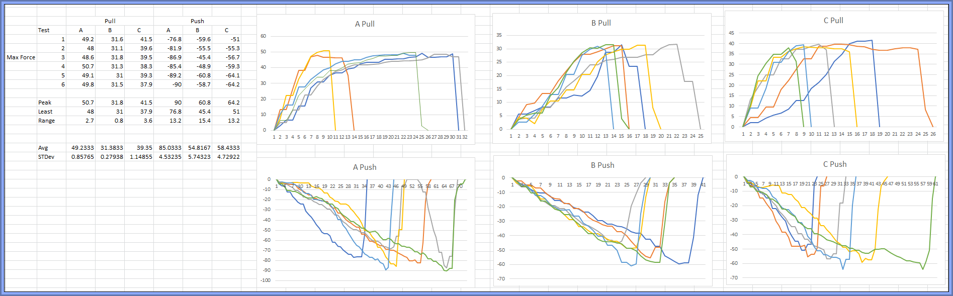
PlayStation A/V Connector - Force Measurement Data
After getting the data, Nick and I needed to distill this down into min/max numbers we could provide to the sub-contracting factory for design verification. We used numbers we found in both the HDMI and USB specifications as rough starting targets since the HDMI Type-A and USB Type-A plugs are of similar physical size and require a similar grip by the end-user. First, we had to quickly study up on the standardized testing method used for HDMI/USB and defined in EIA-364-13. Our force gauge measurements on the PlayStation connectors were not tested the same exact way, so we had to make some minor adjustments to these numbers to account for the difference in test method. We spent a good deal of time playing around with the limits, considering typical uses, worst cases, best cases, and various other nuances. Since we were going to be paying a great deal of money, we wanted good specifications but also needed them to be reasonable and achievable. After a few nights of discussion, the limiting values we settled on were sent to our CM in early Summer 2017 so they could pass them off to the factory.

PlayStation A/V Connector - Desired Force Specifications
The first thing that we heard back was that the price changed to $(even more money), still all upfront. Being out of good options, Nick and I reluctantly agreed and asked for an official quote. In only a short amount of time we were informed by our CM that this factory changed their minds and didn't want to offer this service anymore. This left us with the impression that this factory was toying with us and had no intention of ever doing this, instead quoting high numbers in an attempt to shoo us away. This was a huge bummer, and there was nothing we could do at that point. We had no one else on deck that wanted to take on the job of creating tooling for a new connector, not to mention that we were already behind schedule on getting the PS1 adapter into production. Therefore, this path for designing our own proper PlayStation connector was scrapped. Although a lot of time was seemingly wasted on this approach, we still learned a lot of valuable information in the process.
Chapter IV: A New Hope
It was the end of Summer 2017 at this point. Our last ditch effort was to search on our own for aftermarket connectors, since we were more familiar with what we wanted than our CM was. Nick took photos of the features we wanted (oval indentation & heat-shrink tubing) and spent many late nights chatting with overseas suppliers. While Nick was working on this, I was experimenting on a separate compromise plan which involved removing unused pins from the connector to reduce mating tension. Removing two pins provided a barely noticeable difference, while removing a third was a satisfactory improvement. It was still tight, but no longer a "death-grip". Unfortunately, Nick's quest ended up in nothing except additional bills for sample shipments. Despite pictures from the company that suggested they might have the "good" connector, everything we received was no different than what we already had. It was once again confirmed that the "good" connector was no longer manufactured.
Our only option at this point was the pin-removal approach. To avoid confusion and just to make things simpler, we wanted to use the same connector for the PS2 YPbPr cables we intended to make. Even though the PS2 YPbPr cable can drop some additional connector pins, we were less concerned with PS2 and PS3 console connectors since the fit is way less tight than with PS1 consoles. We asked our CM if they could get the connector supplier to provide the connectors with the pins already removed. At first, they only provided a procedure that our CM's factory would have to follow, but that could result in a significant percentage of damaged connectors. In an attempt to finally move forward on finalizing a solution, we agreed to cover any losses occurred during this process. However, we finally caught a break in this nonstop pummeling of failure, because after some additional negotiations the supplier changed their mind and agreed to remove the pins themselves. We altered our drawings, got revised quotations, and placed an order for the plastics tooling required for both the PS1 adapter and PS2 YPbPr cable.
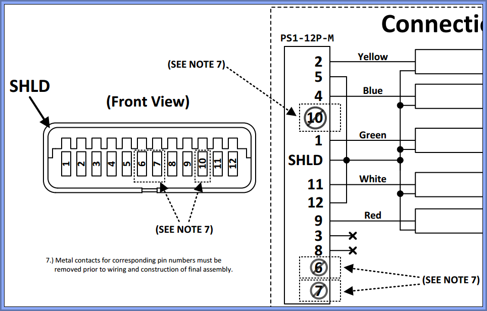
Snip from PS2 YPbPr Cable drawing indicating removal of pins
And that's where we are right now. Samples for the PS1 Adapter and PS2 YPbPr are expected to arrive in January 2018. If everything goes well and they are approved, we will proceed into production. Hopefully all the snags we encountered in this insanely long journey are behind us and we can provide you with solutions for the PlayStation series of consoles very soon.